Coaxial cables are used to transmit radio frequency (RF) signals for telecommunications and television broadcasting. They contain an inner conductor surrounded by an insulating layer and are wrapped in an outer conductor. Coaxial cables need to be highly engineered to minimize signal loss and interference over long distances. The manufacturing process is quite complex and involves multiple steps to create a precise cable structure. This article will provide an overview of the materials, design principles, and manufacturing processes used to create coaxial cable.
Page Contents
- 1 What are the basic parts of a coaxial cable?
- 2 What design factors are considered in coaxial cables?
- 3 What materials are used to make coaxial cables?
- 4 What are the key steps in manufacturing coaxial cable?
- 5 What specialized equipment is used to manufacture coaxial cable?
- 6 What is impedance matching and why is it important?
- 7 What quality control measures are used during coaxial cable production?
- 8 How does shielding work in a coaxial cable?
- 9 Why is the dielectric important in coaxial cable design?
- 10 How does velocity factor relate to signal speed in coaxial cables?
- 11 Why are some coaxial cables more flexible than others?
- 12 What are some examples of special-purpose coaxial cable constructions?
- 13 What are some typical applications of coaxial cable?
- 14 Conclusion
What are the basic parts of a coaxial cable?
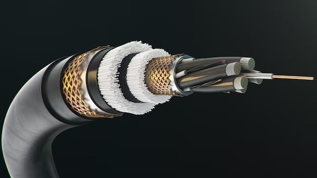
A coaxial cable contains four basic components:
- Inner conductor: A solid or stranded wire that carries the signal. It is usually made of copper.
- Dielectric insulator: An insulating material that surrounds the inner conductor. Common dielectrics are polyethylene, PTFE, and foam polyethylene.
- Outer conductor: A shielding layer of braided copper wires or foil that surrounds the dielectric. This prevents interference from external signals.
- Outer protective jacket: An outer plastic sheath that protects the cable from environmental damage.
The properties and dimensions of each layer are precisely controlled during manufacturing. The insulating dielectric provides separation between the inner and outer conductors. The outer conductor shields the signal on the inner conductor from external electromagnetic interference.
What design factors are considered in coaxial cables?
Coaxial cables are engineered to provide specific electrical properties based on their application. Here are some key design factors:
- Impedance – Cables have a characteristic impedance, typically 50 or 75 ohms, that must match the impedance of devices it connects for efficient power transfer.
- Bandwidth – The range of signal frequencies a cable can transmit without excessive loss or distortion.
- Attenuation – The reduction in signal power/amplitude as it passes through the cable, specified in decibels (dB) per unit length.
- Shielding – Shielding effectiveness describes a cable’s ability to reject external interference.
- Power handling – Larger diameter cables can carry more power with less heating.
- Flexibility – Bend radius determines how tightly a cable can be bent before degrading performance.
Manufacturers optimize these parameters through careful selection of conductor size, dielectric materials, and shield construction when designing cables for a particular application.
What materials are used to make coaxial cables?
Coaxial cables consist of the following raw materials:
- Conductors – High purity copper is nearly always used due to its excellent conductivity and ductility. Silver or aluminum plated copper may be used for inner conductors.
- Insulators – Common dielectrics are polyethylene, polyvinyl chloride (PVC), teflon (PTFE) and air/foam. The dielectric constant affects signal velocity through the cable.
- Shielding – Foil or braided copper wire shields provide 100% coverage against interference. Aluminum or silver plated copper may also be used.
- Jacket – PVC is most common, but jackets can also be polyethylene, teflon, or rubber.
Pure materials and tight quality controls ensure the cable performs to specifications.
What are the key steps in manufacturing coaxial cable?
Coaxial cable production is an automated, high-speed manufacturing process with multiple steps:
- Conductor preparation – Large reels of solid or stranded copper wire are used for the center conductor. The wire surface is cleaned for optimal adhesion.
- Insulation extrusion – The dielectric insulating material is melted and extruded over the inner conductor as both move through a crosshead die. This evenly coats the wire.
- Shielding – Foil shielding is wrapped longitudinally around the insulated conductor. Or, thin copper wires are braided in a complex overlapping pattern over the dielectric for shielding.
- Outer jacket extrusion – The cable passes through another extruder that applies the protective plastic jacket over the shielding.
- Cooling – The hot cable emerging from the extruder is cooled using air or water to set the materials.
- Trimming – A cutting head trims any excess insulating or jacketing materials to precise dimensions.
- Testing – Electronic testing checks cable parameters like impedance, shielding, and signal transmission.
- Packaging – Cables are coiled onto reels or cut to length and packed for shipment.
This continuous in-line process achieves very high productivity rates, while automated testing ensures each meter of cable is built to specifications.
What specialized equipment is used to manufacture coaxial cable?
Modern coaxial cable plants use the following types of automated production equipment:
- Payoff reels – Supply the large reels of inner conductor material to start the process.
- Extruders – Use crosshead dies to apply insulating and jacketing polymers to the conductor.
- Braiders – Interlace fine copper strands around cable cores to form shielding.
- Accumulators – Act as buffers allowing uninterrupted production during material splices.
- Capstans – Provide tension control to pull cables through production lines.
- Cutters – Automated blades trim cables to precise dimensions.
- Testing instruments – Check key parameters like impedance, attenuation, and shielding.
The equipment is controlled by programmable logic controllers (PLCs) that monitor sensors to ensure consistent quality. Production lines can achieve speeds over 1,000 feet per minute with this specialized equipment.
What is impedance matching and why is it important?
Impedance matching is vital for efficient power transfer and minimizing signal reflection in coaxial cables. It involves matching the characteristic impedance of the cable to the impedance of the devices or loads it is connecting. For radio frequency systems, coaxial cables typically have 50 or 75 ohm impedance ratings. This means if the cable is terminated into a load with the same impedance value, power will be completely transferred with no reflection. Mismatched impedances will cause signal reflections that leads to loss and distortion. Careful control of conductor size, dielectric type, and shield materials during manufacturing achieves the target impedance rating.
What quality control measures are used during coaxial cable production?
To guarantee cables meet stringent performance standards, manufacturers employ these quality control procedures:
- Incoming materials inspection – Raw metals and plastics are tested to verify properties.
- Process parameter auditing – Extruder temperatures, line speeds, tensions are controlled.
- Visual inspection – Cameras check for defects and measure dimensions.
- Dimensional tests – Laser micrometers measure cable diameters during production.
- Electrical tests – Instruments continuously measure impedance, signal loss, propagation delay, and shielding.
- HiPot testing – Cables are subjected to high voltage to test insulation integrity.
- Product sampling – Finished cables are destructively tested to confirm performance.
Extensive quality controls throughout the production and testing process results in a very reliable, consistent product.
How does shielding work in a coaxial cable?
Coaxial cables provide excellent shielding against external electromagnetic interference through the combination of complete conductor coverage and skin effect. The braided or foil outer conductor completely surrounds the inner conductor. This prevents external signals from inducing currents in the signal-carrying inner conductor. In addition, skin effect causes high frequency signals to travel only along the outer surface of conductors. So the outer shield conductor effectively blocks any external high frequency signals from penetrating to the core conductor.
Shielding effectiveness is measured in decibels at different frequencies. Additional shield layers can be added and connected to the outer shield at both ends (“double shielding”) for even more protection in high interference environments. Properly grounded shields divert interference safely away from the cable.
Why is the dielectric important in coaxial cable design?
The insulating dielectric used in coaxial cables affects several important electrical characteristics and must be carefully chosen as part of the cable design process:
- It must have strong dielectric properties to prevent current leakage between the conductors.
- The dielectric constant impacts the cable’s impedance. Dielectrics with lower constants like foam result in lower capacitance which increases velocity and bandwidth.
- The dielectric must have low dissipation factor. This means it does not absorb much energy from the signal which causes power loss.
- The insulator must withstand high electric fields without breaking down. Rigid plastics like PTFE perform better than flexible materials here.
- Good mechanical properties are needed to provide a stable center conductor position during bending or vibration.
Common coaxial cable dielectrics like polyethylene and PTFE are engineered to balance these electrical and mechanical requirements.
How does velocity factor relate to signal speed in coaxial cables?
The velocity factor (VF) indicates the speed at which a signal propagates down a coaxial cable compared to the speed of light in a vacuum. Because of the dielectric material separating the conductors, the signal travels slightly slower than light at approximately:
Velocity = Velocity factor x Speed of light
Typical velocity factors range from 66% to 88%. For example, a velocity factor of 66% means the signal speed is 0.66 x c, where c is the speed of light in a vacuum. Polyethylene dielectric has a VF around 0.66, while air dielectric cables have a VF near 1 resulting in very fast signal propagation. Knowing the precise velocity factor allows proper calculation of signal delay in long cables.
Why are some coaxial cables more flexible than others?
Coaxial cable flexibility depends on the specific materials used in construction:
- A solid copper inner conductor limits bending compared to multi-strand conductors.
- Foam dielectrics allow more flexing versus solid insulators.
- Braided copper shields are very flexible versus stiff foil shields.
- PVC jackets are more flexible than teflon or polyehylene.
Critical applications use a helically wrapped outer conductor rather than braiding to maximize flexing without compromising shielding. Flexible cables use corrugated copper shields to allow a tighter bend radius. Cable flexibility is mechanically tested by repeatedly flexing samples through standardized bend radii.
What are some examples of special-purpose coaxial cable constructions?
While standard coaxial cables use copper inner conductors, there are specialty coaxial cable constructions optimized for particular applications:
- Aluminum outer conductor shields reduce weight and cost in aerospace cables.
- Double shielded cables with two braided copper shields provide extra high interference rejection.
- Silver-plated inner conductors improve power handling in high-current applications.
- Low-loss foam dielectrics minimize attenuation in long-run cables.
- Air dielectric cables with polyethylene spiral spacers support ultra-high frequencies.
- Semi-rigid cables using a solid copper outer sheath maintain precise impedance.
- Gas-injected dielectrics prevent cable pressurization problems in submerged uses.
Engineers select specialized constructions to optimize performance and reliability in demanding environments.
What are some typical applications of coaxial cable?
Some common applications utilizing coaxial cable include:
- Television antenna and cable TV signal distribution from 20 MHz to 1 GHz range.
- Cable internet modem and network connections using higher RF frequencies.
- Connecting radio transmitters and receivers to antennas in communications equipment.
- Microwave transmission systems above 1 GHz for data links, satellite networks, and cellular infrastructure.
- High frequency circuit connections between equipment in test labs.
- RF and microwave instrumentation cabling in fields like aerospace, plasma physics, and particle accelerators.
- Feedlines connecting satellite dishes to indoor equipment.
Coaxial cables uniquely combine ability to carry information at high frequencies, protection from interference, and signal purity needed in these applications.
Conclusion
From the center conductor to outer jacket, coaxial cables are engineered to maintain the purity of high frequency signals. Precision materials and manufacturing processes shape a specialized cable structure optimized for shielding, impedance matching, and minimal signal loss. Careful design and testing is needed to meet the demands of modern communication networks. Continued advances in coaxial cable technology will support information transmission well into the future.